

Perhaps you’re inherently curious … perhaps you’re a glutton for punishment.
Perhaps you’re actually looking for the part 1 to this article.
Whatever has brought you here; thanks for stopping by. This is a continuation from the breakdown of a mitre covered previously. In this article we’re about to get involved in the deeper reasons the geometric setups work with some maths. There’s not a lot of ways to spice this up so I won’t blame you if you decide to up and leave before getting through to the end.
As a quick re-cap, we previously looked at an arbitrary angle and then made a mitre to suit. It looked a little something like this;


Started from the bottom, now we’re here.
In practical terms, the previous entry was a pretty comprehensive take on how to measure and markout any mitre. So what exactly are we going to add to that? Well, if you have no interest in a little bit of trigonometry and algebra; probably not a lot. Your time is probably better spent enjoying a different article instead of slogging through this. There are some good photos though.
If you’re ready to take a bit of dive, let’s take this thing back to taws and see what relationships we can start to tease out of our original layout.

Hello darkness my old friend.
Straight off the bat the main relationship we can define here;
θ + σ = 180° … (1)
where;
θ = mitre angle
σ = waste angle
This is great and all but doesn’t initially seem to provide us any more than;
θ = 180° - σ … (2)
σ = 180° - θ … (3)
i.e. the finished mitred angle we want is the straight material minus the waste or visa versa. Something we already knew and the reason this mitre is being worked out; not super handy.
So as before, let’s rotate our frame of reference with respect to σ. Using the extension from the bisection of θ as a baseline we can place the mitre cutout material into our paper space, centred on the bisection of σ.


This 90° relationship will always hold true. Because maths!
Okie Dokie; it’s just such a neat little carve up isn’t it. The mitre has been split in half, such that the waste triangle and the mitre triangle of each half are clearly delineated in a 90° quadrant. We can manipulate (1) to express this in terms of what is observed here;
½ θ + ½ σ = 90° … (4)
Nice. How else can we break this down further down?

Marked up on the waste and material aspects of the mitre (magenta & blue respectively) are the triangles that makes up the cut. We can see that these are actually the same triangle; or more concisely; these two triangles are congruent and out of rotation by 180°. We can also go ahead and define some more angles;
α = ½ θ … (5)
φ = ½ σ … (6)
α + φ = 90° … (7)
ω = σ + α … (8)
or, conversely
ω = 180° - α … (9)
You might recognise here that α and ω are actually the angles the bevel would typically be set at to markout the mitre. Seeing the angles laid out like this, with respect to the edge of the material and the waste should make it clear why either of these work for the markout;
α is exaclty half of the mitre angle (from (5))
ω is half of the mitre angle plus the waste angle, (from (8))
You might ask why σ was the focus here and not θ. This is a reasonable question with a straight answer. It’s far easier to visualise how this joint works by examining it with respect to σ. Of course, the material can be arranged on our setout with respect to θ and this still satisfies the above equations. I think it just doesn’t come across as intuitive to look at terms of θ. Laid out as above, it’s easy to use your mind’s eye to rotate the right hand piece through the waste to complete the angle; it’s almost a spontaneous reaction to seeing it arranged this way. Below, for comparison, is how the material looks set out with respect to θ.

This way, to mentally finish the mitre, it has to move through the waste angle + a further 180°. Not as immediately intuitive as the previous layout.
At this point; we’ve carved pretty much all the meat off how our example mitre applies to its own relationships. But there are still a few nuggets of understanding that can be gleaned about mitres in general. As with in life in general, the more exciting stuff is found at the limits. So what are they?
Looking back to (1); θ + σ = 180°, we can see that the sum of our two angles will always equal 180°. Because the two angles are related in this way, we can also see that as one approaches 180° the other must approach 0° to satisfy (1). From this we can infer the upper and lower limits as 180° & 0° respectively. To quickly scrutinize this, let’s try exceeding the bounds; let θ > 180°. In this instance, the only way to satisfy (1) would require σ < 0°; i.e. a negative angle. Not practically possible for a mitre. The reverse also holds true, i.e. θ < 0°.
To start visually examining the limits, we’ll begin by observing θ as it approaches 0° and 180°. To better illustrate what the lines mean, I’ll include worked cutouts to clearly demonstrate these in more discernible terms.
Firstly, let’s look at θ as it approaches 180°. What do we see here?

As paperspace only, it’s not much to look at so, let’s go ahead with some markup and cuts for the mitre on a piece of material.


Still not a lot to write home about
Okay so we can see is that in practice, this would represent a minor change of direction. Not particularly hard to visualise and you might even have seen some similar moulding like this in your travels.
Now let’s flip this around and look at θ as it approaches 0°.

From before, you may now be able to visualise that this would be quite a sharp change of direction. So sharp in fact, that when bisected and transferred onto the bevel, the saw can’t close up to cut it.


dayum
A different method is needed to make this cut. Again this could be by hand or circular saw, but I’m going to use a bandsaw. Firstly we’ll mark and cut this on material that’s at the same scale to which we’ve currently been working.


Let’s check that out on the page.


The two pieces are too small to create the mitre. I have placed them into θ, along with the waste cut out in σ, to illustrate how these arranged triangles (waste + material) still equal 180°.
The second shot showing only the waste on the markout demonstrates that σ now encompasses the lion’s share of the material. A pretty clear visual illustration of how θ approaching 0° means σ approaches 180°; still satisfying (1).
Of course, this demonstration wouldn’t be complete without actually making this mitre so let’s go ahead and rip that out.


Yeah, missed it by that much on the first crack
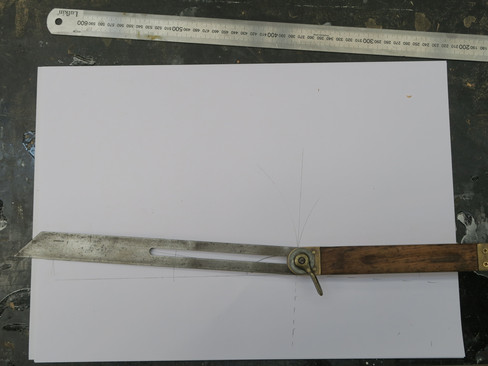
To put some scale to this, I have been marking out on A3 pages and the visible straight edge is 600mm (2ft) long; there's a fair bit of gear making up that mitre. This could reasonably be considered pretty extreme as external mitres go; but these types of long tapered cuts are used for particular applications. Think inlaid floor medallions or stepped changes of direction for horizontal boards, like boardwalks.


How ‘bout those mitred toe boards.
Also, unfortunately I don’t know anyone with a floor medallion to provide a good photo.
Now, we’ve looked at θ approaching the limits and our equations have held up; so far, so good. The examples should hopefully also be assisting in making the lines on the page represent something tangible and what these angles and limits actually mean. For the next step, let’s go ahead and scrutinize the upper limit;
Let θ = 180° & σ = 0°
What exactly does this look like?

Yeah, the photo just doesn’t do it justice.
I’ll admit; there’s not a lot to get excited about there. We can still bisect this angle with our compass, so what does that look like?

In this instance, there is no crossover of the arcs. We can tell we have reached the limit because the two arcs only touch tangentially to create our bisection point. This bisection now gives us a line that is perfectly perpendicular to our material θ, which creates two 90° halves of θ with 0° of σ.
Is there anything else good on there? We could try bisecting each side again I guess.

Am I losing my mind, this is starting to look like a Rorschach test
In terms of θ = 180° these additional lines, bisecting the bisection, are practically useless. To make this more visible, let’s look at some material on the page with the initial bisection marked.

We know that σ = 0°. What we can observe here is that θ = 180° literally relates to a straight piece of material with no cuts or changes of direction. Why then, has it taken a couple thousand words to get to this point? That, I can’t give you a more detailed answer on.
From above now though, we can flip this around such that;
θ = 0° & σ = 180°

Hang on a sec, I think I’ve seen this before. Are we going around in circles here?
Verily! That right there is the whole shooting match. Where σ = 180° there is no mitre left. We could go ahead and bisect this in the same was as before, but half of nothing is the same as all of nothing; so there’s no point really.

Ta-Da
Yeah right, thanks for that. Speaking of points, what was the point of the 2nd bisection before?
Good question. Let’s step back to our marked out θ = 180° example, only now I’ll place a couple of squares on top.

Okay. We knew that the initial bisection was at 90° to the material. By bisecting this angle again, we have created four (4) equal angles at 45°. We can also see that in any 180° plane we can always evenly divide this into four angles of 45°. In fact, if we took that page and rotated, flipped or mirrored it; the geometry of the 180° plane always divides evenly into four angles of 45°no matter what.


Let’s go ahead and place our 180° stick back on the page; this time with the extra bisection marked.

We’re definitely going around in circles.
Indeed, this layout now very much resembles our initial 90° mitre layout from part 1. One of the reasons the square, the shape, is such a useful means of construction is because of this highly symmetrical quality.

It is for this reason that a square, the tool, can be placed on any edge of material that is parallel, and mirrored or flipped in any way while still creating a 90° corner as an outcome.


Okay, you’ve definitely taken me to my limits with this thing now
That pretty much sums up all I can practically think of regarding mitres. A real under the hood if you will, and quite the road-trip as well. If you managed to hang on, thanks for riding this one out with me. It did get a little dense in there; from about paragraph two I was told. But you know me; if it’s worth doing, it’s worth overdoing.
Looking forward to a breezier journey next time.
Kind Regards
Walker
June 2021
If you liked this article why not stay up to date with all the latest from Timber Tone. Click here to subscribe so you never miss a post or video.
コメント