

The humble mitre is one of the simplest joints that can be made. They aren’t a particularly strong joint, but are quick to make and aesthetically pleasing when done correctly. In general they’re a no muss, no fuss kind of deal but actually understanding how these joints are formed is interesting and will help tackle any arbitrary angle that you mitre end up coming across.
First up, what is a mitre? Most simply;
A joint between two pieces of material where the intersection bisects the joint in half.
Cool. So where do they go?
Generally speaking, there are three main shapes employed for building things; squares, circles and triangles. The buildings we inhabit and the structures we create, have a tendency towards being square; as squares are useful shapes, with straight edges and easily bisected corners. They are so prevalent that dedicated tools, ‘squares’, are literally devoted to checking for and bisecting a square.
It’s hip to be square.
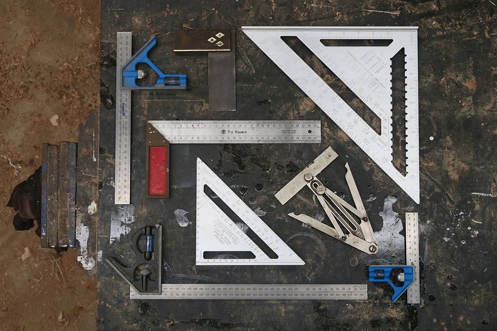
The various assortment of squares can make for quick work when assembling a 90° mitre. They come in a few different orientations and formats but all function to serve basically similar purposes. Looking at them, it seems intuitive that one edge does the square bit and the other edge does the half the angle joining part. Let’s kick things off by looking at how the different facets of a square set up a 90° mitre.
Starting with material that is square & parallel, we’ll pick a face edge and then look to incorporate an internal and external mitre. To locate these, I’ve just marked a centreline for each.
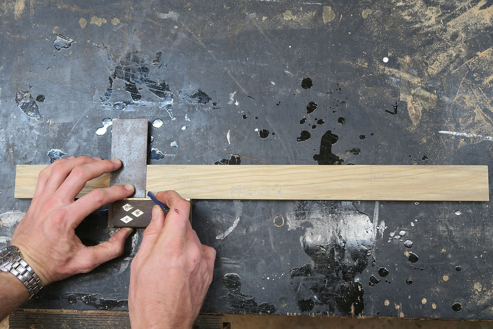
As an internal or external mitre, the layout of this joint is essentially the same. Being that this material is also square & parallel, the only really important thing to consider is the face side of the piece and marking the waste out accordingly. For an internal mitre, we’re looking to remove material from the front to ‘push’ the material ‘into’ a space. For an external mitre we need to remove material from the back to ‘pull’ the material ‘around’ an edge. As such, an internal mitre could be said to ‘shrink in’ while an external ‘wraps around’. How do we go about doing this, let’s see.


mark and flip and flip and mark
Using whatever way of thinking about it floats your boat; i.e. push/pull, shrink/wrap or something else entirely, to locate the joint, use the angled part of the square blade to markout from the centre line. This creates a triangle for each mitre, centred on the line, with the longest edge of this triangle on the waste side. It’s important to mark this on the correct side of the piece as it isn’t too hard to get turned around sometimes while doing this. When looked at, the internal and external markout will mirror each other with respect to the edge. Time to cut it out.


Quite satisfying seeing it laid back out in pieces
The cuts can be done with a hand or circular saw or in a machine, like bandsaw or mitre-drop saw. The drop saw is far and away the cleanest and fastest way to do this. Most drop saws will come with positive stops to suit a 45° cut but it’s still a good idea to check and set the blade with one of your squares. Laying the pieces back out, the waste triangles are really clearly defined, and our sample is looking the business. However, for some extra clarity, let’s add a little bit of context to help visualise what it is we’re looking at and wanting to achieve.
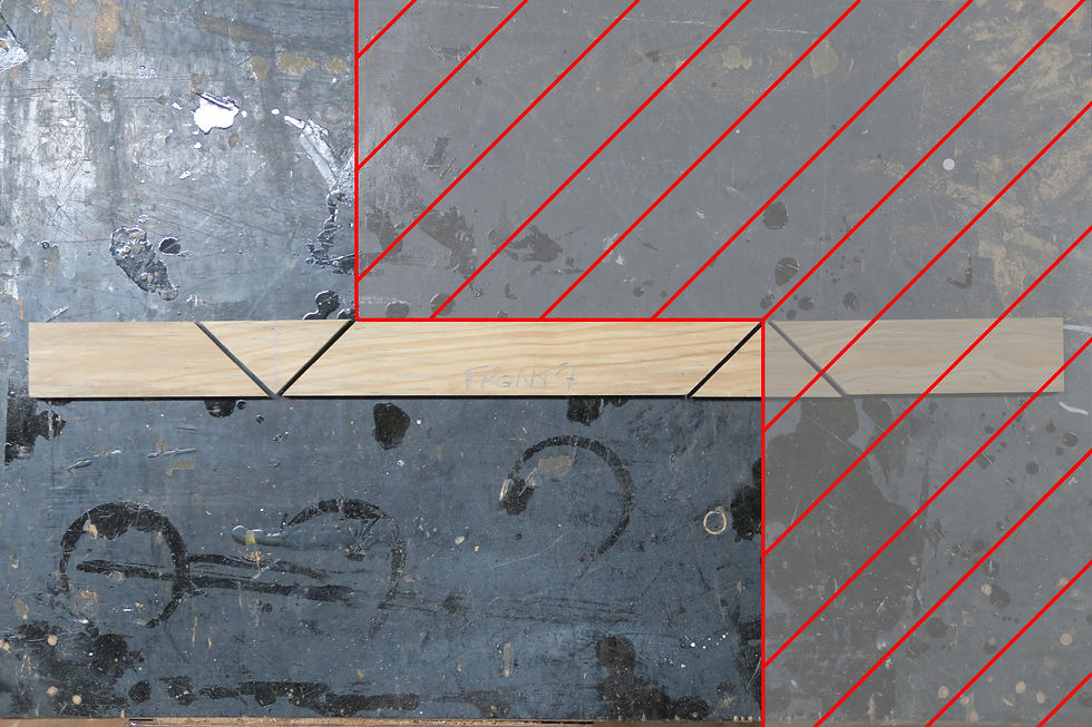
Picture the hatched area as some solid thing, a wall say, that needs our stick needs fitted to it. Imagine now, that the tips where the cutouts of our material meet are hinge points and the loose outside section will rotate around until the faces meet. Visualising it in this way may help flesh out our little adage from before of shrinking in and wrapping around. So how’s it look actually pieced together?
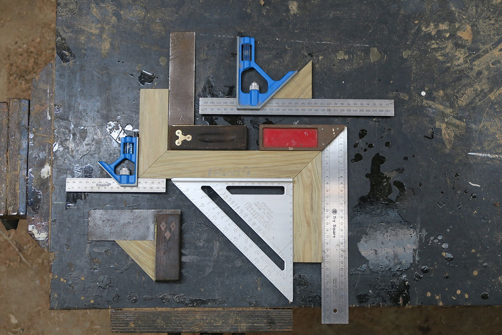
There’s a little bit to unpack here
Our single straight stick from before has become three pieces fitted around our ‘wall’. The inner and outer corners of each mitre are finished at a crisp 90° with a neatly bisecting joint line at 45°. Looking at the two waste triangles we can see these are each 45° right angle triangles. Overall a successful little exercise for making 90° corners.
Of course, this is all well and good but did you know that in reality, buildings are not built to ultra-high tolerances *gasp*. They also include angles that are not 90° *swoon*. With the above bit of basic knowledge however, we can start to look at tackling mitres of any angle.
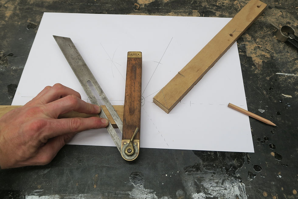
The first thought when dealing with such mitres might still be to just only use the angled edge on the square. We know it’s the one that is used for joint making, right? From before though, we can see that this will create a 90° corner; not our desired angle. So how do you approach this? Specialty tools are available to measure, bisect & transfer different angles. I snuck a Stanley No. 30 Angle Divider into the squares squared photo above; but you may not have something like this on hand. Let’s look at how, employing only a couple of simple hand tools, the geometry of a mitre can be extracted without using any math calcs.
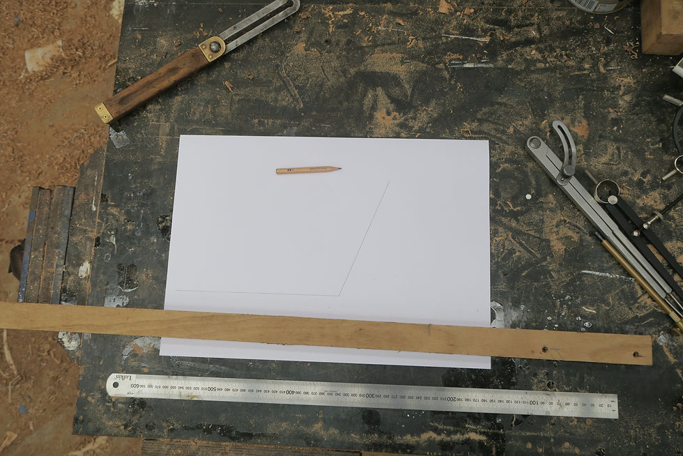
So it begins
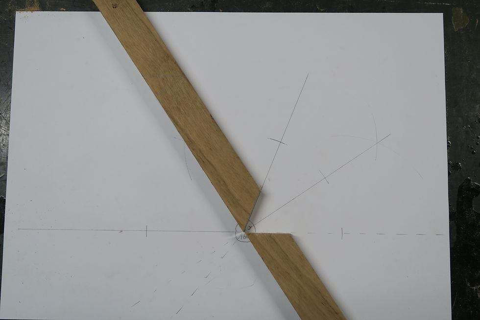
To do this, a bevel, straight edge & compass or divider are all that is required, along with the piece of material being mitred. I’ve drawn an arbitrary angle onto the paper for this exercise. In practice, the bevel would be placed and fitted onto/into the angle we need to mitre, then used to transfer this onto paper or some flat surface to be worked out.
We can see the angle required and have a single straight piece of material to create it with. To ensure the finished form is neat; we need to split this angle in half, achieving a mirroring effect between the two finished pieces. We before observed this in practice; the 45° blade on the square created our 90° mitre; as 45° is half of 90°. So, we can confirm from our earlier definition and example, that the intersection of the joint angle is half of the total angle.
But how do we go about dividing this angle in half? This is where the compass/divider comes in.
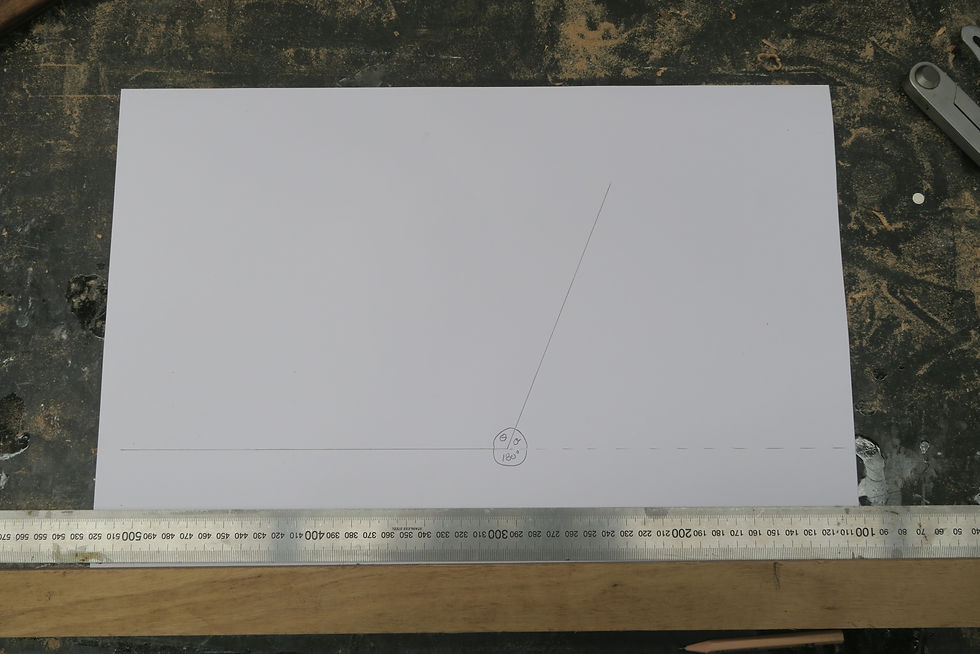
Firstly, I’ve extend one of the lines outwards to create a 180° plane. Either will work and I have opted for the horizontal one for ease of display. This isn’t critical but will help later. I have also labelled the two angles on the page as; theta (θ) for our mitre and sigma (σ) for the supplementary angle. At the moment this isn’t important and we’ll refer to the point at which these meet as the zero-point.


As this is a paper I’ll utilise a compass for this exercise. Take the compass and pick an arbitrary radius. Anything will do here, the only real requirement is that it has to fit on the page comfortably. Place the needle of the compass on the zero-point and make a mark where the radius touches each of the two lines of the mitre angle. Now place the needle of the compass on each of these newly created intersections and draw a short arcs in the approximate centre of the mitre angle.
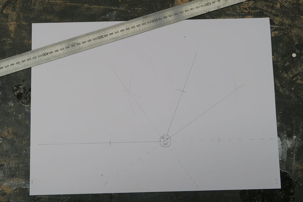
Use the straight edge to line up the intersection of the arcs and the zero-point, then draw a straight line. You’ll note that I have bisected both angles here and added continuations past the base line. For the moment, we are only concerned with the bisected mitre angle on the left. This newly created line perfectly divides the mitre in half. Meaning right now, we have all we need to create this mitre. For those punters ready to rip into making something; this is where the magic is at.


But wait there’s more… Two for the price of one!


You sure this is still regulation?
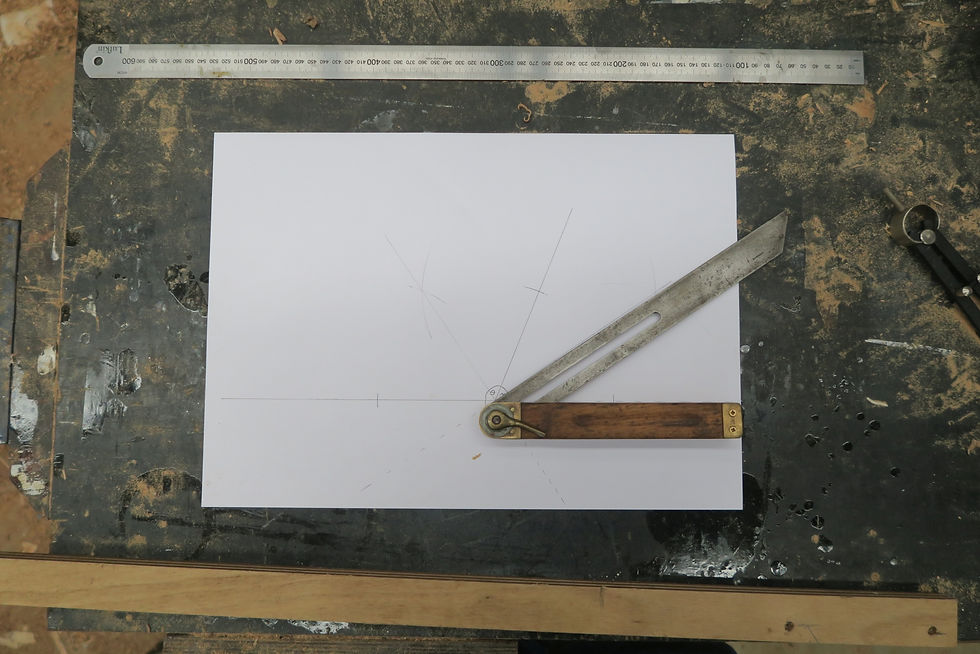
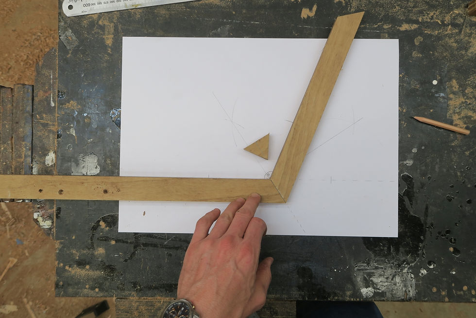
Set to either orientation above, the bevel can be mirrored on the same edge or flipped to the opposite edge of the material to markout both halves of the mitre. For now we’ll just refer to these as the acute (first one) and obtuse (second one). I personally prefer the obtuse layout as opposed to the acute one. I find it a bit easier to see when using it to setup the saw. Some circumstances may require each orientation to be employed to complete the markup and/or cutout. We can also see that the acute orientation is half of the mitre angle; so we should automatically expect this to work. The obtuse however, is half of the angle plus some. Ehhh?


Righto; you lot here only for the answers, on your bikes and get making.
Everyone else, stay awhile and listen.
Everything you need to know to practically measure and mark any mitre angle has now been covered; so feel free to use this as your off ramp if you need. Thanks for reading. There is still some good stuff to be looked at here though; so feel free to hang on. You might even learn some more.
We’ve now twice seen demonstrated that the mitre joint angle is half of the total angle; why this works though, takes a little more explanation. To look a little deeper, we’ll move our focus to the waste angle, sigma σ. I have already bisected this angle so let’s go ahead and set our bevel up to ‘half of this included angle’.
Mmmmmhh, yeah looks good. Whatdya actually do with it?
Okay, so what does this actually do for us? Most plainly, this angle comprises half of the waste from the mitre. We saw before in the markout, that the triangular waste cutout was split in half by the centreline we were marking around. What may not be immediately apparent is how this triangular cutout can be thought of in relation to how it interacts with the mitre angle. To make this relationship clearer, let’s re-arrange how to think about the material by shifting our frame of reference towards the waste portion of the mitre. Using the line bisecting our mitre angle and its continuation marked earlier as a baseline, we’ll place the already mitred material along this to illustrate the waste in real terms.
Well, there you go.
Including this visual context on how the waste relates to the mitre we have already cut, creates a quite a clear perspective of how everything interacts. I previously bisected the waste angle and we can see the even split of the waste between each half of the mitre. We could also deduce then, that using the bevel set to half of the waste as above, should also create the correct mitre angle. It may not be immediately intuitive as to where to place the tool though. Using the waste bisection line as a guide, we can see that the tool can be placed at 90° to the edge, i.e. on a square end, to create the mark for one half of the joint. This application is really only convenient insofar as having stock or some other reason where the end or a perpendicular line is the only practical means of marking out from.
Not particularly common.
So, we could refer to this as our acute setting like before; but what about the obtuse or supplementary part of this angle? We previously saw that either bevel orientation for the mitre would suffice for the markout; how then, does that work here?
In short, it doesn’t. In practical terms, the supplement to this angle is basically useless. It can be created and observed within our paper space markout, but it really only demonstrably exists within this Euclidean space.


Euclidean space you say … *eyes glaze over*
Indeed, this is where the practical and the abstract are starting to cross-over; feel free to use this point as your exit to go and get making. The layout and tool setups described above are all that is required to work out, mark and cut repeatable mitres for any angle. Thanks for hanging on; have fun & success with your next mitring project.
You’ll nail it now ;)
For anyone wanting some further insight into why these angles work, feel free to slog your way through part 2. Prior to posting, the most positive feedback I received was ‘like swimming through treacle’. What's not to love. Enjoy!
Until the next dip.
Kind Regards
Walker
June 2021
If you liked this article why not stay up to date with all the latest from Timber Tone. Click here to subscribe so you never miss a post or video.
Comments